Toggle Nav


Electric Retract Landing Gear Controller & MANUAL For JP Hobby Retract Gear
$78.00
Availability:
In stock
SKU
PR-ERC2
SPECIFICATIONS AND FEATURES:
- Operating voltage: 7.4v – 8.4v (Direct from 2s Lipo battery)
- Low voltage cut off: Auto gear down if battery drops below 7.4v
- Controls gear, brakes and up to three gear doors
- Fine tuning available for the electric brakes to assure a straight line upon braking
- Four options for gear door sequencing
- Optional ABS braking
Safety feature: “Gear Up” incorporates a 4 second delay before gear is actually retracted.During this time an audible buzzer is activated warning the user of the imminent retraction of the gear,allowing time to reverse the process if due to an accidental “Gear Up” while still on the ground.
INCLUDED HARDWARE:
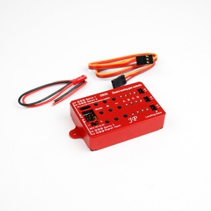
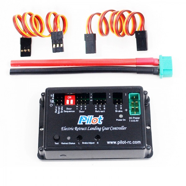
- One Electric Retract Landing Gear Controller
- Patch leads
WARNING:
- Do not exceed the maximum voltage of 8.4v or equivalent 2s Lipo
2- Installation and setup
INITIAL INSTALLATION AND SETUP:
1.Setup two channels on your radio with the desired switches/sliders to control each channel (one for the retracts and one for the brakes)
2.Set both channels end point travels to -100% and +100%
3.Locate on the Electric Retract Landing Gear Controller the Radio inputs for Gear and Brake, and connect to the corresponding receiver channels set up in step 1 using the patch leads provided.
4.Connect the Retract leads and Brake leads to the Electric Retract Landing Gear Controllers corresponding outputs.
5.Fine tuning of the brakes can be achieved using the + and – buttons to assure a linear braking of the model.
6.Push the test button for a few seconds, this will cycle the gear by either retracting or extending. You can use this testing button at any time, allowing for easy gear up after you have finished flying for the day.
Please note that the testing button is designed to work only when the receiver is turned OFF.
7.Make sure that the gear operating direction is correct. The gear should go from extended to retracted shortly after the audible alarm. If the gear is up and goes down after audible alarm, please reverse the connector for the Retract leads (reverse the polarity)
Can also be confirmed by the incorporated status LED: Red is retracts up, green is retracts down.
8.Alarm. If the input voltage drops to 7.4v or less, the gear will automatically extend for a safe landing position. An audible buzzer will also buzz repeatedly and continuously warning of this low battery status.
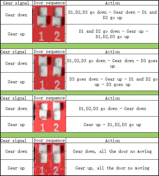
GEAR DOOR SEQUENCER:
Select the desired gear door movements from the four options below, and move the sliders following your chosen diagram.
Please note that the signals for Gear Door 1 and Gear Door 2 are opposites, which should suite most installations. If however you require both Gear Door actuators to work in the same direction, please simply use a Y lead and take both signals from the same port.
The controller can not adjust the end points of the Gear Doors, for this please proceed to adjust mechanically using different length servo arms, push rods or control horns to obtain the required travel.
Write Your Own Review
Check items to add to the cart or